Login with root to LibreELEC or OpenELEC.
# mkdir -p /storage/.xbmc/media/Fonts
or
# mkdir -p /storage/.kodi/media/Fonts
Upload truetype font to this path.
Reboot again.
# mkdir -p /storage/.xbmc/media/Fonts
or
# mkdir -p /storage/.kodi/media/Fonts
Name:   gpio-fan
Info:   Configure a GPIO pin to control a cooling fan.
Load:   dtoverlay=gpio-fan,<param>=<val>
Params: gpiopin                 GPIO used to control the fan (default 12)
        temp                    Temperature at which the fan switches on, in
                                millicelcius (default 55000)
Reference: https://github.com/raspberrypi/firmware/tree/master/boot/overlays
dtoverlay=gpio-fan,gpiopin=12,temp=55000temp = 55000 is millicelcius
#!/bin/bash
GPIO_PIN=12
HIGH_TEMP=50000
SAVE_TEMP=45000
function get_temp() {
cat /sys/class/thermal/thermal_zone0/temp
}
function gpio_enable() {
echo $1 > /sys/class/gpio/export
}
function gpio_disable() {
echo $1 > /sys/class/gpio/unexport
}
function gpio_set_output() {
echo out > /sys/class/gpio/gpio$1/direction
}
function gpio_set_input() {
echo in > /sys/class/gpio/gpio$1/direction
}
function gpio_set_on() {
echo 1 > /sys/class/gpio/gpio$1/value
}
function gpio_set_off() {
echo 0 > /sys/class/gpio/gpio$1/value
}
function cleanup() {
QUIT=1
}
QUIT=0
#echo "Enable GPIO ${GPIO_PIN}"
gpio_enable $GPIO_PIN
#echo "Set GPIO ${GPIO_PIN} Output"
gpio_set_output $GPIO_PIN
#echo "set GPIO ${GPIO_PIN} on"
#gpio_set_on $GPIO_PIN
LASTSTATUS=0
trap cleanup SIGINT SIGTERM
while [ 1 ]; do
cputemp=$(get_temp)
#echo "CPU TEMP = $cputemp"
if [ $LASTSTATUS = 0 ]; then
if [ $cputemp -gt $HIGH_TEMP ]; then
echo "FAN ON"
echo "CPU TEMP = $cputemp"
gpio_set_on $GPIO_PIN
LASTSTATUS=1
fi
else
if [ $cputemp -lt $SAVE_TEMP ]; then
echo "FAN OFF"
echo "CPU TEMP = $cputemp"
gpio_set_off $GPIO_PIN
LASTSTATUS=0
fi
fi
if [ "$QUIT" = "1" ]; then break; fi
sleep 1
done
#echo "set GPIO ${GPIO_PIN} off"
gpio_set_off $GPIO_PIN
#echo "Disable GPIO ${GPIO_PIN}"
gpio_disable $GPIO_PIN
$ chmod 755 /home/pi/bin/temp_montior
$ sudo nano /etc/rc.local
...
/home/pi/bin/temp_monitor &
...
exit0
Name:   gpio-shutdown
Info:   Initiates a shutdown when GPIO pin changes. The given GPIO pin
        is configured as an input key that generates KEY_POWER events.
        This event is handled by systemd-logind by initiating a
        shutdown. Systemd versions older than 225 need an udev rule
        enable listening to the input device:

                ACTION!="REMOVE", SUBSYSTEM=="input", KERNEL=="event*", \
                        SUBSYSTEMS=="platform", DRIVERS=="gpio-keys", \
                        ATTRS{keys}=="116", TAG+="power-switch"

        This overlay only handles shutdown. After shutdown, the system
        can be powered up again by driving GPIO3 low. The default
        configuration uses GPIO3 with a pullup, so if you connect a
        button between GPIO3 and GND (pin 5 and 6 on the 40-pin header),
        you get a shutdown and power-up button.
Load:   dtoverlay=gpio-shutdown,<param>=<val>
Params: gpio_pin                GPIO pin to trigger on (default 3)

        active_low              When this is 1 (active low), a falling
                                edge generates a key down event and a
                                rising edge generates a key up event.
                                When this is 0 (active high), this is
                                reversed. The default is 1 (active low).

        gpio_pull               Desired pull-up/down state (off, down, up)
                                Default is "up".

                                Note that the default pin (GPIO3) has an
                                external pullup.
Reference: https://github.com/raspberrypi/firmware/tree/master/boot/overlays
dtoverlay=gpio-shutdown,gpio_pin=3,active_low=1,gpio_pull=up
ACTION!="REMOVE", SUBSYSTEM=="input", KERNEL=="event*", \
                        SUBSYSTEMS=="platform", DRIVERS=="gpio-keys", \
                        ATTRS{keys}=="116", TAG+="power-switch"


$ dmesg
[ 14.665558] bluetooth hci0: Direct firmware load for rtl_bt/rtl8723b_config.bin failed with error -2
[ 14.665824] bluetooth hci0: Direct firmware load for rtl_bt/rtl8723b_fw.bin failed with error -2
[ 14.665842] Bluetooth: hci0: Failed to load rtl_bt/rtl8723b_fw.bin
$ lsusbI found.
Bus 001 Device 004: ID 0bda:b720 Realtek Semiconductor Corp.
$ sudo apt-get install raspberrypi-kernel-headers git build-essential
$ mkdir drivers
$ cd drivers
$ git clone https://github.com/lwfinger/rtl8723bu.git
$ cd rtl8723bu
$ sed -i "s/^EXTRA_CFLAGS += -DCONFIG_CONCURRENT_MODE/#EXTRA_CFLAGS += -DCONFIG_CONCURRENT_MODE/g" Makefile
$ make
$ sudo make install
$ echo "options 8723bu rtw_power_mgnt=0 rtw_enusbss=0" | sudo tee /etc/modprobe.d/8723bu.conf
$ git clone https://github.com/lwfinger/rtl8723au_bt.git
$ cd rtl8723au_bt/Linux_BT_USB_2.11.20140423_8723BE/8723B
$ sudo cp rtl8723b_config /lib/firmware/rtl_bt/rtl8723b_config.bin
$ sudo cp rtl8723b_fw /lib/firmware/rtl_bt/rtl8723b_fw.bin
$ hcitool scan
Scanning ...
XX:XX:XX:XX:XX:XX xxxxxx
XX:XX:XX:XX:XX:XX xxxxxx
$ ifconfig
wlan0: flags=4099<UP,BROADCAST,MULTICAST> mtu 1500
ether xx:xx:xx:xx:xx:xx txqueuelen 1000 (Ethernet)
RX packets 17 bytes 0 (0.0 B)
RX errors 0 dropped 80 overruns 0 frame 0
TX packets 0 bytes 0 (0.0 B)
TX errors 0 dropped 0 overruns 0 carrier 0 collisions 0
$ echo -e "ctrl_interface=DIR=/var/run/wpa_supplicant GROUP=netdev\nupdate_config=1\ncountry=TH\n\n" | sudo tee /etc/wpa_supplicant/wpa_supplicant-wlan0.confAdd SSID and Password of Accesspoint to wpa_supplicant config file
$ wpa_passphrase test 12345678 | sudo tee -a /etc/wpa_supplicant/wpa_supplicant-wlan0.conf


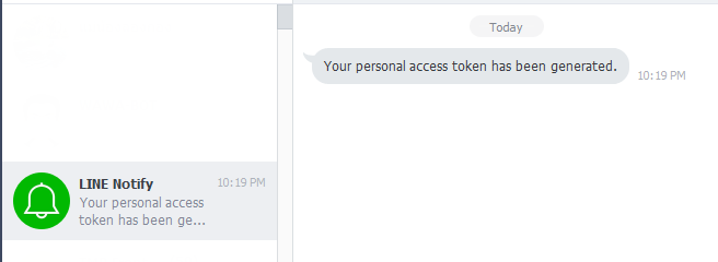
After run this curl command. You will receive message 'Hello' to LINE Instant Messenger via LINE Notifycurl -k -X POST -H 'Authorization: Bearer [access_token]' -F 'message=hello' https:// notify-api.line.me/api/notify

**file path to image = Image file Supported image format is png and jpegcurl -k -X POST -H 'Authorization: Bearer [access_token]' -F 'message=hello' -F 'imageFile=@[**file path to image]' https:// notify-api.line.me/api/notify

mkdir /data/script
#!/bin/bash
curl -k -X POST -H 'Authorization: Bearer [access_token]' -F "message=$1" https://
notify-api.line.me/api/notify
#!/bin/bash
curl -k -X POST -H 'Authorization: Bearer [access_token]' -F "message=$1" -F "imageFile=@$2" https://
notify-api.line.me/api/notify
chmod 755 linenotify_push.sh
chmod 755 linenotify_pushimage.sh
/data/script/linenotify_push.sh "Good world"
/data/script/linenotify_pushimage.sh "Good Job" "/data/output/Camera1/test.jpg"

/data/script/linenotify_push.sh "Motion Detect at %Y-%m-%d %H-%M-%S"

/data/script/linenotify_push.sh "Motion Detect End at %Y-%m-%d %H-%M-%S"


/data/script/linenotify_push.sh "Motion Detect at %Y-%m-%d %H-%M-%S" %f


hdmi_force_hotplug=1
hdmi_group=2
hdmi_mode=1
hdmi_mode=87
# 1024 x 600
hdmi_cvt 1024 600 60 6 0 0 0
max_usb_current=1
hdmi_force_hotplug=1
hdmi_group=2
hdmi_mode=1
hdmi_mode=87
#800x480
hdmi_cvt 800 480 60 6 0 0 0
max_usb_current=1


$ sudo apt-get update
$ sudo apt-get install libpcre3-dev libatomic-ops-dev libgeoip-dev geoip-bin geoip-database geoip-database-extra libperl-dev libssl-dev libxml2-dev libxslt1-dev
$ mkdir src
$ cd src
$ wget http://nginx.org/download/nginx-1.9.5.tar.gz
$ tar -xvzf nginx-1.9.5.tar.gz
$ git clone https://github.com/arut/nginx-rtmp-module.git
$ cd nginx-1.9.5
$ ./configure --prefix=/usr/local/nginx --user=www-data --group=www-data --with-select_module --with-poll_module --with-threads --with-file-aio --with-ipv6 --with-http_ssl_module --with-http_realip_module --with-http_addition_module --with-http_xslt_module --with-http_image_filter_module --with-http_geoip_module --with-http_sub_module --with-http_dav_module --with-http_flv_module --with-http_mp4_module --with-http_gunzip_module --with-http_gzip_static_module --with-http_auth_request_module --with-http_random_index_module --with-http_secure_link_module --with-http_degradation_module --with-http_stub_status_module --with-http_perl_module --with-mail --with-mail_ssl_module --with-pcre --with-pcre-jit --with-md5-asm --with-sha1-asm --with-libatomic --with-pcre --with-stream --with-stream_ssl_module --with-http_v2_module --add-module=../nginx-rtmp-module
$ make
$ sudo make install
$ sudo nano /usr/local/nginx/conf/nginx.conf
$ sudo /usr/local/nginx/sbin/nginx
$ sudo /usr/local/nginx/sbin/nginx -s stop
$ sudo nano /etc/modprobe.d/8192cu.conf
options 8192cu rtw_power_mgnt=0 rtw_enusbss=0
$ sudo apt-get install minidlna
Add pi user to minidlna group
$ sudo usermod -a -G minidlna pi
Create Directory for store media file
Example:
$ mkdir -p /home/pi/minidlna/music
$ mkdir -p /home/pi/minidlna/pictures
$ mkdir -p /home/pi/minidlna/videos
$ mkdir -p /home/pi/.minidlna
Change Mode of /home/pi/minidlna and /home/pi/.minidlna
$ sudo chmod 777 /home/pi/minidlna
$ sudo chmod 777 /home/pi/.minidlna
Config MiniDLNA
$ sudo nano /etc/minidlna.conf
Modify this file
...
db_dir=/home/pi/.minidlna/data
log_dir=/home/pi/.minidlna/data/log
# * "A" for audio (eg. media_dir=A,/var/lib/minidlna/music)
# * "P" for pictures (eg. media_dir=P,/var/lib/minidlna/pictures)
# * "V" for video (eg. media_dir=V,/var/lib/minidlna/videos)
media_dir=A,/home/pi/minidlna/music
media_dir=P,/home/pi/minidlna/pictures
media_dir=V,/home/pi/minidlna/videos
# Name that the DLNA server presents to clients.
friendly_name=RASPBERRY DLNA
# Automatic discovery of new files in the media_dir directory.
inotify=yes# Notify interval, in seconds.notify_interval=895...
Restart MiniDLNA Service
$ sudo /etc/init.d/minidlna restart
Or re-indexing all of media files
$ sudo /etc/init.d/minidlan force-reload
Test on Device supported with DLNA/UPnP to play media.
Reference:
Digital Living Network Alliance
https://en.wikipedia.org/wiki/Digital_Living_Network_Alliance
ReadyMedia (MiniDLNA Source Code)
http://sourceforge.net/projects/minidlna/
ReadyMedia (Wiki of Archlinux)
https://wiki.archlinux.org/index.php/ReadyMedia


dtoverlay=lirc-rpi***For new kernel***
dtoverlay=gpio-ir
dtoverlay=lirc-rpi,gpio_out_pin=17,gpio_in_pin=18
dtoverlay=gpio-ir,gpio_pin=18,gpio_pull=up
# killall lircd
# irrecord /storage/.config/lircd.conf
irrecord - application for recording IR-codes for usage with lirc Copyright (C) 1998,1999 Christoph Bartelmus(lirc@bartelmus.de) This program will record the signals from your remote control and create a config file for lircd. A proper config file for lircd is maybe the most vital part of this package, so you should invest some time to create a working config file. Although I put a good deal of effort in this program it is often not possible to automatically recognize all features of a remote control. Often short-comings of the receiver hardware make it nearly impossible. If you have problems to create a config file READ THE DOCUMENTATION of this package, especially section "Adding new remote controls" for how to get help. If there already is a remote control of the same brand available at http://www.lirc.org/remotes/ you might also want to try using such a remote as a template. The config files already contain all parameters of the protocol used by remotes of a certain brand and knowing these parameters makes the job of this program much easier. There are also template files for the most common protocols available in the remotes/generic/ directory of the source distribution of this package. You can use a template files by providing the path of the file as command line parameter. Please send the finished config files toso that I can make them available to others. Don't forget to put all information that you can get about the remote control in the header of the file. Press RETURN to continue. Now start pressing buttons on your remote control. It is very important that you press many different buttons and hold them down for approximately one second. Each button should generate at least one dot but in no case more than ten dots of output. Don't stop pressing buttons until two lines of dots (2x80) have been generated. Press RETURN now to start recording. ................................................................................ Found const length: 107201 Please keep on pressing buttons like described above. ................................................................................ Space/pulse encoded remote control found. Signal length is 67. Found possible header: 8951 4451 Found trail pulse: 572 Found repeat code: 8961 2214 Signals are space encoded. Signal length is 32 Now enter the names for the buttons. Please enter the name for the next button (press to finish recording) KEY_POWER Now hold down button "KEY_POWER". Please enter the name for the next button (press to finish recording) KEY_1 Now hold down button "KEY_1". Please enter the name for the next button (press to finish recording) KEY_2 Now hold down button "KEY_2". Please enter the name for the next button (press to finish recording) KEY_3 Now hold down button "KEY_3". Please enter the name for the next button (press to finish recording) ...
# irrecord --list
KEY_POWERAfter finish all key. Press Enter for finished.
KEY_1
KEY_2
KEY_3
KEY_4
KEY_5
KEY_6
KEY_7
KEY_8
KEY_9
KEY_0
KEY_VOLUMEUP
KEY_VOLUMEDOWN
KEY_MUTE
KEY_EXIT
KEY_CHANNELUP
KEY_CHANNELDOWN
KEY_INFO
KEY_UP
KEY_LEFT
KEY_RIGHT
KEY_DOWN
KEY_OK
KEY_MENU
KEY_AUDIO
KEY_VIDEO
KEY_BACKSPACE
KEY_PLAY
KEY_PAUSE
KEY_FORWARD
KEY_STOP
KEY_RADIO
KEY_TEXT
KEY_TITLE
# shutdown -r now
