Showing posts with label Raspberry PI. Show all posts

Tuesday, March 5, 2019

Install font to LibreELEC or OpenELEC

How to install new font to LibreELEC or OpenELEC

Login with root to LibreELEC or OpenELEC.

# mkdir -p /storage/.xbmc/media/Fonts
or
# mkdir -p /storage/.kodi/media/Fonts

Upload truetype font to this path.

Reboot again.


Tuesday, September 25, 2018

Shutdown Button with Device Tree Overlays

I want to create shutdown button for raspberry pi.
I found gpio-shutdown parameter for enable Device Tree Overlays on new firmware.

Name:   gpio-shutdown
Info:   Initiates a shutdown when GPIO pin changes. The given GPIO pin
        is configured as an input key that generates KEY_POWER events.
        This event is handled by systemd-logind by initiating a
        shutdown. Systemd versions older than 225 need an udev rule
        enable listening to the input device:

                ACTION!="REMOVE", SUBSYSTEM=="input", KERNEL=="event*", \
                        SUBSYSTEMS=="platform", DRIVERS=="gpio-keys", \
                        ATTRS{keys}=="116", TAG+="power-switch"

        This overlay only handles shutdown. After shutdown, the system
        can be powered up again by driving GPIO3 low. The default
        configuration uses GPIO3 with a pullup, so if you connect a
        button between GPIO3 and GND (pin 5 and 6 on the 40-pin header),
        you get a shutdown and power-up button.
Load:   dtoverlay=gpio-shutdown,<param>=<val>
Params: gpio_pin                GPIO pin to trigger on (default 3)

        active_low              When this is 1 (active low), a falling
                                edge generates a key down event and a
                                rising edge generates a key up event.
                                When this is 0 (active high), this is
                                reversed. The default is 1 (active low).

        gpio_pull               Desired pull-up/down state (off, down, up)
                                Default is "up".

                                Note that the default pin (GPIO3) has an
                                external pullup.
Reference: https://github.com/raspberrypi/firmware/tree/master/boot/overlays


Step to create shutdown switch

  • Connect switch to GPIO3.


  • Add config device tree overlays on /boot/config.txt.


dtoverlay=gpio-shutdown,gpio_pin=3,active_low=1,gpio_pull=up


  •  Create file /etc/udev/rules.d/99-gpio-power.rules


ACTION!="REMOVE", SUBSYSTEM=="input", KERNEL=="event*", \
                        SUBSYSTEMS=="platform", DRIVERS=="gpio-keys", \
                        ATTRS{keys}=="116", TAG+="power-switch"


  • And restart raspberry pi.


After reboot success. I try to push switch.
It works ;). My raspberry pi is shutdown.

Hope to help you.

*** I2C must be deactivated if you use pin 3. (Thank you @Irmoreno007)

Wednesday, July 25, 2018

Mantistek WA150 (WIFI+Bluetooth) RTL8723BU

I buy Mantistek WA150 to use on Raspberry PI. It has both WIFI and Bluetooth.


The raspbian kernel version 4.14.52+ #1123. It hasn't driver to use it.

I use command.

$ dmesg

I found. Raspbian can detect bluetooth device but it isn't have firmware. (rtl8723b_fw.bin)

[   14.665558] bluetooth hci0: Direct firmware load for rtl_bt/rtl8723b_config.bin failed with error -2
[   14.665824] bluetooth hci0: Direct firmware load for rtl_bt/rtl8723b_fw.bin failed with error -2
[   14.665842] Bluetooth: hci0: Failed to load rtl_bt/rtl8723b_fw.bin

I use command for check usb device id.

$ lsusb
I found.
Bus 001 Device 004: ID 0bda:b720 Realtek Semiconductor Corp.

The USB Device ID is 0bda:b720.

I search device id for identify device. I found RTL8723BU (not RTL8723AU).

I found driver and firmware.

 WIFI Driver (Source code)


Bluetooth Firmware


Install Step
First step. Install linux kernel header package and other package for raspbian.
$ sudo apt-get install raspberrypi-kernel-headers git build-essential

Create directory for build source and download source code

$ mkdir drivers
$ cd drivers

Install RTL8723BU WIFI Driver
$ git clone https://github.com/lwfinger/rtl8723bu.git
$ cd rtl8723bu

Disable Concurrent Mode
$ sed -i "s/^EXTRA_CFLAGS += -DCONFIG_CONCURRENT_MODE/#EXTRA_CFLAGS += -DCONFIG_CONCURRENT_MODE/g" Makefile

Build and Install
$ make
$ sudo make install

Disable power save
$ echo "options 8723bu rtw_power_mgnt=0 rtw_enusbss=0" | sudo tee /etc/modprobe.d/8723bu.conf

Install RTL8723B Bluetooth Driver

$ git clone https://github.com/lwfinger/rtl8723au_bt.git
$ cd rtl8723au_bt/Linux_BT_USB_2.11.20140423_8723BE/8723B
$ sudo cp rtl8723b_config /lib/firmware/rtl_bt/rtl8723b_config.bin
$ sudo cp rtl8723b_fw /lib/firmware/rtl_bt/rtl8723b_fw.bin

And restart raspberry pi

Test bluetooth scan with command.

$ hcitool scan
Scanning ...
          XX:XX:XX:XX:XX:XX       xxxxxx
          XX:XX:XX:XX:XX:XX       xxxxxx

It work.

And check WIFI interface with command.

$ ifconfig

It work. I found wlan0 interface.

wlan0: flags=4099<UP,BROADCAST,MULTICAST>  mtu 1500
        ether xx:xx:xx:xx:xx:xx  txqueuelen 1000  (Ethernet)
        RX packets 17  bytes 0 (0.0 B)
        RX errors 0  dropped 80  overruns 0  frame 0
        TX packets 0  bytes 0 (0.0 B)
        TX errors 0  dropped 0 overruns 0  carrier 0  collisions 0

And try to config wpa_supplicant-wlan0.conf for wlan0 interface

$ echo -e "ctrl_interface=DIR=/var/run/wpa_supplicant GROUP=netdev\nupdate_config=1\ncountry=TH\n\n" | sudo tee /etc/wpa_supplicant/wpa_supplicant-wlan0.conf
 Add SSID and Password of Accesspoint to wpa_supplicant config file
$ wpa_passphrase test 12345678 | sudo tee -a /etc/wpa_supplicant/wpa_supplicant-wlan0.conf

And restart raspbian. Finish step.

Have a good day everyone. 😎


Reference:
WIFI Driver (Source code)
Bluetooth Firmware
Realtek RTL8723BU


Wednesday, October 11, 2017

motionEyeOS (Raspberry PI) push video and image to dropbox

motionEyeOS can send video and image to cloud storage (Google Drive and Dropbox)

This topic will storage them to Dropbox.


  • Login to motionEyeOS

  • Select File Storage Section
  • Enable Upload Media Files, Upload Pictures and Upload Movies
  • On Upload Service. Select Dropbox.
  • On Location. Select Folder on Dropbox for save video and image. (If don't have folder, go to dropbox create new folder before config motionEyeOS)

  • Click on Obtain Key. It will go to Dropbox for generate Authorization key.

  • Allow Authorization. and copy Authorization key.
  • Enter Authorization key on Authorization key form and click Test service button
  • After success. click on apply for save all config. 


If you enable Motion Detection for record video or save images, after record finish or save images finish. It will push video and image push to Dropbox automatic.

Hope you enjoy with it. 😊

Tuesday, October 10, 2017

motionEyeOS (Raspberry PI) notification via LINE Notify

motionEyeOS (CCTV Software)

motionEyeOS is A Video Surveillance OS For Single-board Computers


motionEyeOS Source: https://github.com/ccrisan/motioneyeos
motionEye Source: https://github.com/ccrisan/motioneye

Download motionEyeOS Image: https://github.com/ccrisan/motioneyeos/releases

motionEyeOS Wiki: https://github.com/ccrisan/motioneyeos/wiki

How to install can see at Raspberry PI Spy (https://www.raspberrypi-spy.co.uk/2017/04/raspberry-pi-zero-w-cctv-camera-with-motioneyeos/)


LINE Instant Messager

LINE Notify Service: https://notify-bot.line.me/en/


  • Login with LINE Account

  • Select menu My page


  • Select Generate Token button

  • Enter token name and select 1-on-1 chat with LINE Notify or Group for send notification
  • Select Generate Token button

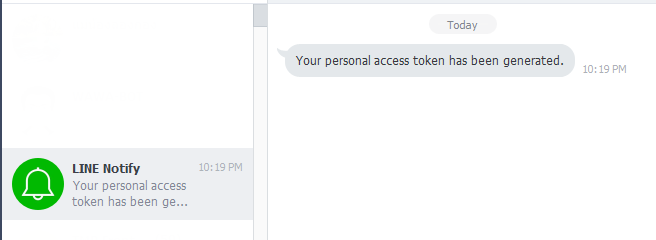
  • I will show token for send notification. copy it. and select close button

  • In LINE Instant Messenger will have LINE Notify Account add to you.  


Test send notify with curl
curl -k -X POST -H 'Authorization: Bearer [access_token]' -F 'message=hello' https://  
notify-api.line.me/api/notify
After run this curl command. You will receive message 'Hello' to LINE Instant Messenger via LINE Notify


If you want to send Message and Image to LINE Instant Messager, you can curl with this command.

curl -k -X POST -H 'Authorization: Bearer [access_token]' -F 'message=hello' -F 'imageFile=@[**file path to image]' https://  
notify-api.line.me/api/notify
**file path to image = Image file Supported image format is png and jpeg
Image will upload to server for send notification.


More Information
LINE Notify API Document: https://notify-bot.line.me/doc/en/
LINE Engineer Blog: https://engineering.linecorp.com/en/blog/detail/88


Create script for send notification on motionEyeOS

  • create directory /data/script with command
mkdir /data/script
  • create shell script
File: /data/script/linenotify_push.sh

#!/bin/bash
curl -k -X POST -H 'Authorization: Bearer [access_token]' -F "message=$1" https://
notify-api.line.me/api/notify

File: /data/script/linenotify_pushimage.sh

#!/bin/bash
curl -k -X POST -H 'Authorization: Bearer [access_token]' -F "message=$1" -F "imageFile=@$2" https://
notify-api.line.me/api/notify

  • change mode of file to executable file.

chmod 755 linenotify_push.sh
chmod 755 linenotify_pushimage.sh

Test script file


/data/script/linenotify_push.sh "Good world"

It will receive "Good world" message at LINE Instant Message

/data/script/linenotify_pushimage.sh "Good Job" "/data/output/Camera1/test.jpg"

It will receive "Good Job" message and test.jpg image at LINE Instant Message.

Now. You can run script for sent notification.


Use notification script at motionEyeOS

  • Login on motionEyeOS

  • Go to Motion Notifications section

  • Enable Run A Command (Send notification if motionEyeOS detect motion on camera)
  • On command box enter command

/data/script/linenotify_push.sh "Motion Detect at %Y-%m-%d %H-%M-%S"


  • (Option) If you want to send notification after finish motion detect, Enable Run An End Command and  enter command.

/data/script/linenotify_push.sh "Motion Detect End at %Y-%m-%d %H-%M-%S"


  • If you want to send image of motion detect, go to Still Images section.
  • Select capture mode to Motion Triggered or Motion Triggered (One Picture).

  • go to File storage.
  • Enter command on Run An Command 
/data/script/linenotify_push.sh "Motion Detect at %Y-%m-%d %H-%M-%S" %f

  • go to Motion Detection Section. Enable Motion Detection


  • Select Apply button on top to apply all config.


If motion detect of motionEyeOS detected, I will send "Motion Detect at [Date and Time]" message to LINE Instant Message.

After finish with motion detect (nothing movement) Send "Motion Detect End at [Date and Time]" message to LINE Instant Message.

and Send "Motion Detect at [Date and Time]" message " and image file to send to LINE Instant Message


Wednesday, May 25, 2016

Waveshare 7inch HDMI LCD (C) and 5inch HDMI LCD (B) on NOOBS

HDMI LCD

Waveshare 7 inch HDMI LCD (C)

Waveshare 5 inch HDMI LCD (B)


NOOBS (Raspberrry PI)


First write NOOBS Image to SD Card.
After finished.

Create file config.txt on NOOBS SDCard. (It don't have config.txt on NOOBS image)

config.txt  (for 7 inch HDMI LCD (C))

hdmi_force_hotplug=1
hdmi_group=2
hdmi_mode=1
hdmi_mode=87
# 1024 x 600
hdmi_cvt 1024 600 60 6 0 0 0
max_usb_current=1
If you use the LCD with Raspberry Pi 4 B, you need to remove the line dtoverlay=vc4-fkms-V3D from config.txt file

Wiki for 7 inch HDMI LCD (C)
http://www.waveshare.com/wiki/7inch_HDMI_LCD_%28C%29

config.txt (for 5 inch HDMI LCD (B))

hdmi_force_hotplug=1
hdmi_group=2
hdmi_mode=1
hdmi_mode=87
#800x480
hdmi_cvt 800 480 60 6 0 0 0
max_usb_current=1
Save it. and eject from computer.
Try to boot with Raspberry PI to test it.


All image on NOOBS should change config.txt for support this HDMI LCD Device.

Enjoy ;)


Reference:
NOOBS (Raspberrry PI)

Friday, March 25, 2016

Live TV DVB-T2 with VDR Addons on OpenELEC

I have Geniatech DVB-T2 Stick T220.
I use OpenELEC to play Live TV with it.


Current version of OpenELEC is 6.0.3.

First install services add-ons VDR PVR Backend.
Goto: System -> Settings -> Add-ons -> Install from repository -> OpenELEC Add-ons (offical) -> Services -> VDR PVR Backend


Install VDR PVR Backend

After Installed. Go back to PVR clients.

Install VDR VNSI Client (If VDR VNSI Client is not installed)

Select Configure of VDR VNSI Client.

Enable create channel groups automatically on the server And OK.

Next Goto Home -> Programs -> VDR Configuration


Select Channel scanner Configuration


Start scanning TV channel.
Select 
  • Tuner Type: DVB-T
  • Country: <your location>
  • Cleanup all
And Start


After scan completed. Select Close.

Enable TV menu on OpenELEC
Goto: Home -> System -> Settings -> TV

Select Enable:  General -> Enabled and Synchronis channel groups with backend(s)


Go back to Home and Select TV

Now already to watch Live TV from DVB-T2 Device and recording.

Have a good day. :)


Addition:

VDR PVR Backend has other plugins to use.
You can enable on configure menu.

Goto: Home -> System -> Settings -> Add-ons -> Install from repository -> OpenELEC Add-ons (offical) -> Services -> VDR PVR Backend

Select Configure.

You can enable other plugins if you want to use.


Reference:
VDR - The Video Disk Recorder

VDR Wiki

Monday, October 5, 2015

How to compile nginx with nginx-rtmp-module

Prepare environment for compile.
$ sudo apt-get update
$ sudo apt-get install libpcre3-dev libatomic-ops-dev libgeoip-dev geoip-bin geoip-database geoip-database-extra libperl-dev libssl-dev libxml2-dev libxslt1-dev

Create directory src

$ mkdir src

Download Nginx (last version)

$ cd src
$ wget http://nginx.org/download/nginx-1.9.5.tar.gz
$ tar -xvzf nginx-1.9.5.tar.gz

Git Clone nginx-rtmp-module

$ git clone https://github.com/arut/nginx-rtmp-module.git


Change current to nginx-1.9.5

$ cd nginx-1.9.5

Run configure

$ ./configure --prefix=/usr/local/nginx --user=www-data --group=www-data --with-select_module --with-poll_module --with-threads --with-file-aio --with-ipv6 --with-http_ssl_module --with-http_realip_module --with-http_addition_module --with-http_xslt_module --with-http_image_filter_module --with-http_geoip_module --with-http_sub_module --with-http_dav_module --with-http_flv_module --with-http_mp4_module --with-http_gunzip_module --with-http_gzip_static_module  --with-http_auth_request_module --with-http_random_index_module --with-http_secure_link_module --with-http_degradation_module --with-http_stub_status_module --with-http_perl_module --with-mail --with-mail_ssl_module --with-pcre --with-pcre-jit --with-md5-asm --with-sha1-asm --with-libatomic --with-pcre --with-stream --with-stream_ssl_module --with-http_v2_module --add-module=../nginx-rtmp-module

Run make to compile

$ make

Install nginx to /usr/local/nginx

$ sudo make install

Config Nginx on /usr/local/nginx/conf/nginx.conf

$ sudo nano /usr/local/nginx/conf/nginx.conf


Config for streaming server see on nginx-rtmp-module wiki

Web path /usr/local/nginx/html

Start nginx service

$ sudo /usr/local/nginx/sbin/nginx

Stop nginx service

$ sudo /usr/local/nginx/sbin/nginx -s stop


Reference
Nginx

nginx-rtmp-module (source code)

nginx-rtmp-module (wiki)

Streaming with nginx-rtmp-module


Wednesday, September 30, 2015

How to Disable Power Management of rtl8192cu

Fix problem wireless disconnect and go to save mode.

Create file /etc/modprobe.d/8192cu.conf

$ sudo nano /etc/modprobe.d/8192cu.conf

add this line

options 8192cu rtw_power_mgnt=0 rtw_enusbss=0


Restart raspberry pi


Reference :

https://github.com/xbianonpi/xbian/issues/217

https://github.com/pvaret/rtl8192cu-fixes/blob/master/8192cu-disable-power-management.conf

DLNA/UPnP with MiniDLNA

How to build DLNA/UPnP Server on Raspberry PI for use at Home device.
(Example TV, Media player, PS3, Xbox etc.)


Install minidlna package

$ sudo apt-get install minidlna


Add pi user to minidlna group

$ sudo usermod -a -G minidlna pi

Create Directory for store media file

Example:

$ mkdir -p /home/pi/minidlna/music
$ mkdir -p /home/pi/minidlna/pictures
$ mkdir -p /home/pi/minidlna/videos
$ mkdir -p /home/pi/.minidlna

Change Mode of /home/pi/minidlna and /home/pi/.minidlna
$ sudo chmod 777 /home/pi/minidlna
$ sudo chmod 777 /home/pi/.minidlna

Config MiniDLNA

$ sudo nano /etc/minidlna.conf

Modify this file
...
db_dir=/home/pi/.minidlna/data
log_dir=/home/pi/.minidlna/data/log
# * "A" for audio (eg. media_dir=A,/var/lib/minidlna/music)
# * "P" for pictures (eg. media_dir=P,/var/lib/minidlna/pictures)
# * "V" for video (eg. media_dir=V,/var/lib/minidlna/videos)
media_dir=A,/home/pi/minidlna/music
media_dir=P,/home/pi/minidlna/pictures
media_dir=V,/home/pi/minidlna/videos
# Name that the DLNA server presents to clients.
friendly_name=RASPBERRY DLNA
# Automatic discovery of new files in the media_dir directory.
inotify=yes
# Notify interval, in seconds.notify_interval=895...

Restart MiniDLNA Service

$ sudo /etc/init.d/minidlna restart

Or re-indexing all of media files

$ sudo /etc/init.d/minidlan force-reload


Test on Device supported with DLNA/UPnP to play media.


Reference:

Digital Living Network Alliance
https://en.wikipedia.org/wiki/Digital_Living_Network_Alliance

ReadyMedia (MiniDLNA Source Code)
http://sourceforge.net/projects/minidlna/

ReadyMedia (Wiki of Archlinux)
https://wiki.archlinux.org/index.php/ReadyMedia

Saturday, July 18, 2015

VNC Server for Raspberry PI with dispmanx

You can remote console of raspberry pi with dispmanx


Install libvncserver-dev, gcc and g++ version 4.7

$ sudo apt-get install gcc-4.7 g++-4.7 libvncserver-dev

Update alternatives version of gcc and g++

$ sudo update-alternatives --install /usr/bin/gcc gcc /usr/bin/gcc-4.6 60 --slave /usr/bin/g++ g++ /usr/bin/g++-4.6

$ sudo update-alternatives --install /usr/bin/gcc gcc /usr/bin/gcc-4.7 40 --slave /usr/bin/g++ g++ /usr/bin/g++-4.7

Select gcc and g++ version to 4.7 (2)

$ sudo update-alternatives --config gcc
There are 2 choices for the alternative gcc (providing /usr/bin/gcc).

Selection Path Priority Status
------------------------------------------------------------
* 0 /usr/bin/gcc-4.6 60 auto mode
1 /usr/bin/gcc-4.6 60 manual mode
2 /usr/bin/gcc-4.7 40 manual mode

Press enter to keep the current choice[*], or type selection number: 2
update-alternatives: using /usr/bin/gcc-4.7 to provide /usr/bin/gcc (gcc) in manual mode
See on : https://github.com/Na1w/dispmanx_vnc

Clone source code of dispmanx.
$ git clone https://github.com/Na1w/dispmanx_vnc.git

Compile dispmanx.

$ cd dispmanx_vnc
$ make
After compile finish. It has dispmanx_vncserver file.
Copy this file to execute path. example /bin, /usr/local/bin, etc.


If you want to use X, modprobe  evdev first.

$ sudo modprobe evdev
See on : https://github.com/hanzelpeter/dispmanx_vnc


Start dispmanx vncserver

$ sudo dispmanx_vncserver
*** default port 5900

Stop dispmanx vncserver with Control + C Key.


Start dispmanx vncserver with password

$ sudo dispmanx_vncserver -P [password]

Change port number

$ sudo dispmanx_vncserver -p [port number]


Screen resolution config on /boot/config.txt

Example (1280x1024)
#HDMI force hotplug
hdmi_force_hotplug=1
# Group DMT
hdmi_group=2
# mode 35 - 1280x1024 60Hz
hdmi_mode=35
Reboot after save config.

Reference:

dispmanx_vnc
https://github.com/hanzelpeter/dispmanx_vnc

https://github.com/Na1w/dispmanx_vnc

Raspberry PI Document configuration config.txt
https://www.raspberrypi.org/documentation/configuration/config-txt.md

Thursday, July 16, 2015

How to use VNC Server on Raspberry PI

If you want to remote to Raspbian with X Windows Desktop, you can use vnc server.

Install TightVNC Server.

$ sudo apt-get install tightvncserver

After install finished.

Start vncserver.

$ tightvncserver :<DISPLAY NUMBER>

Example: Start VNC Server on Display number 1 or port 5901 run with pi user.
$ tightvncserver :1

You will require a password to access your desktops.

Password: 
Verify: 

Would you like to enter a view-only password (y/n)? n


New 'X' desktop is raspberrypi:1


Creating default startup script /home/pi/.vnc/xstartup

Starting applications specified in /home/pi/.vnc/xstartup

Log file is /home/pi/.vnc/raspberrypi:1.log

On first time run script. Program will ask password for connect to VNC Server and ask view-only mode for this password.


After run tightvncserver. You can use TightVNC Viewer or VNC Client for remote to server.

Enter IP Address : Display number and Connect


Enter Password and OK

Connected to VNC Server


If you want to change vnc password for remote, use this command.
$ tightvncpasswd
Using password file /home/pi/.vnc/passwd
Password:
Verify:
Would you like to enter a view-only password (y/n)? n

VNC Password File save on /<User Directory>/.vnc/passwd


Stop VNC Server

$ tightvncserver -kill :<DISPLAY NUMBER>

Example : Stop VNC Server Display number 1

$ tightvncserver -kill :1

Screen resolution of VNC.
Start VNC Server with option.

$ tightvncserver -geometry <width>x<height> -depth <color depth>

Example

$ tightvncserver -geometry 1280x720 -depth 16 :1

Reference :

TightVNC
http://tightvnc.org/


Tuesday, July 7, 2015

How to use DS3231 I2C Real Time Clock


Before use DS3231 I2C Real Time Clock. Enable I2C Interface.

On new kernel use Device Tree Overlays.

Edit on /boot/config.txt.

add new line

device_tree_param=i2c1=on
dtoverlay=i2c-rtc,ds3231

Reference : https://github.com/raspberrypi/firmware/tree/master/boot/overlays

Edit on /etc/modprobe.d/raspi-blacklist.conf

add # (comment) on line "blacklist i2c-bcm2708"

#blacklist i2c-bcm2708

Reboot Raspberry PI

sudo shutdown -r now

Re-Check I2C Interface software

$ dmesg | grep i2c
[    5.505513] bcm2708_i2c 20804000.i2c: BSC1 Controller at 0x20804000 (irq 79) (baudrate 100000)
[   11.969815] i2c /dev entries driver

$ lsmod
i2c_bcm2708             6244  0

If you found, software is enabled.


Install DS3231 I2C RTC to Raspberry PI


Test to get time from RTC Module.

$ sudo hwclock -r 
Tue 07 Jul 2015 05:20:09 PM ICT  -0.397656 seconds 

If you want to current time of Raspberry PI to RTC Module.

$ sudo hwclock -w

If you want to set time of RTC Module to Raspberry PI.

$ sudo hwclock -s

You can set time of RTC Module to Raspberry PI on startup.

Edit on file /etc/rc.local
Add line

/sbin/hwclock -s

before line "exit 0"


Reference :
Device Tree overlays of Raspberry PI Firmware
https://github.com/raspberrypi/firmware/tree/master/boot/overlays
Adding a hardware clock to Raspberry Pi (DS3231)
http://www.drewkeller.com/blog/adding-hardware-clock-raspberry-pi-ds3231
Adding a DS3231 Real Time Clock To The Raspberry Pi
http://www.raspberrypi-spy.co.uk/2015/05/adding-a-ds3231-real-time-clock-to-the-raspberry-pi/
Using an I2C Real Time Clock (RTC) with a Raspberry Pi
https://nicegear.co.nz/blog/using-an-i2c-real-time-clock-rtc-with-a-raspberry-pi/

How to use RFID-RC522 on Raspbian


Before use RFID-RC522. Enable SPI Interface (Update 2018-09-28)

Current kernel in document (Raspbian GNU/Linux 9 Kernel Version 4.14.70-v7+ #1144)

Enable SPI Interface
- Use command
$ sudo raspi-config
select menu
5 Interfacing Options -> SPI -> Yes -> OK -> Finish
Or

- Edit on /boot/config.txt.

change this line

dtparam=spi=on


Edit on /etc/modprobe.d/raspi-blacklist.conf

add # (comment) on line "blacklist spi-bcm2708"

#blacklist spi-bcm2708

Reboot Raspberry PI

sudo shutdown -r now

Re-Check SPI Interface software

$ dmesg | grep spi
[    5.408904] bcm2708_spi 20204000.spi: master is unqueued, this is deprecated
[    5.659213] bcm2708_spi 20204000.spi: SPI Controller at 0x20204000 (irq 80)

$ lsmod | grep spi
spidev                 16384  0
spi_bcm2835            16384  0


If you found, software is enabled.

Install Software for use RFID-RC522
Install python-dev

sudo apt-get install python-dev

Install SPI-Py (Hardware SPI as a C Extension for Python)

git clone https://github.com/lthiery/SPI-Py.git
cd SPI-Py
sudo python setup.py install

Install MFRC522-python

git clone https://github.com/mxgxw/MFRC522-python.git 
cd MFRC522-python 

Install Python RC522 library

$ git clone https://github.com/ondryaso/pi-rc522.git
$ cd pi-rc522
$ sudo python setup.py install


Install Pins between Raspberry PI and RFID-RC522

RFID-RC522 Pin
 Raspberry PI Pin
Raspberry PI Pin name
SDA
  24
    GPIO8
SCK
  23
    GPIO11
MOSI
  19
    GPIO10
MISO
  21
    GPIO9
IRQ
  18
    GPIO24
GND
  Any
    Any Ground
RST
  22
    GPIO25
3.3V
  1
    3V3

You can test read card.

$ cd examples
$ python Read.py
Starting

If touch the card, it will display.

Detected: 10
Card read UID: XX,XX,XX,XX
Setting tag
Selecting UID [XX, XX, XX, XX, XX]

Authorizing
Changing used auth key to [XX, XX, XX, XX, XX, XX] using method B

Reading
Calling card_auth on UID [XX, XX, XX, XX, XX]
S1B0: [0, 0, 105, 36, 64, 0, 0, 0, 0, 0, 0, 0, 0, 0, 0, 0]

Deauthorizing
Changing auth key and method to None
^C
Ctrl+C captured, ending read.

And test write card.

$ python KeyChange.py
Starting

Detected: 10
Card read UID: XX,XX,XX,XX
Setting tag
Selecting UID [XX, XX, XX, XX, XX]

Authorizing
Changing used auth key to [255, 255, 255, 255, 255, 255] using method A

Writing modified bytes
Calling card_auth on UID [XX, XX, XX, XX, XX]
Changing pos 2 with current value 0 to 105
Changing pos 3 with current value 0 to 36
Changing pos 4 with current value 0 to 64
Writing [0, 0, 105, 36, 64, 0, 0, 0, 0, 0, 0, 0, 0, 0, 0, 0] to S1B0
Not calling card_auth - already authed
S1B0: [0, 0, 105, 36, 64, 0, 0, 0, 0, 0, 0, 0, 0, 0, 0, 0]
Calling card_auth on UID [XX, XX, XX, XX, XX]
Changing pos 0 with current value 0 to 18
Changing pos 1 with current value 0 to 52
Changing pos 2 with current value 0 to 86
Changing pos 3 with current value 0 to 120
Changing pos 4 with current value 0 to 150
Changing pos 5 with current value 0 to 146
Changing pos 6 with current value 255 to 15
Changing pos 7 with current value 7 to 7
Changing pos 8 with current value 128 to 143
Changing pos 9 with current value 105 to 105
Changing pos 10 with current value 255 to 116
Changing pos 11 with current value 255 to 0
Changing pos 12 with current value 255 to 82
Changing pos 13 with current value 255 to 53
Changing pos 14 with current value 255 to 0
Changing pos 15 with current value 255 to 255
Writing [18, 52, 86, 120, 150, 146, 15, 7, 143, 105, 116, 0, 82, 53, 0, 255] to S1B3
Changing auth key and method to None
Stopping crypto1

You can learning python code for use RFID read and write data.


Python RC522 library : https://github.com/ondryaso/pi-rc522


Example Project for use NFC and Raspberry PI


  • Attendance system using Raspberry Pi and NFC Tag reader by Yim

http://www.instructables.com/id/Attendance-system-using-Raspberry-Pi-and-NFC-Tag-r/


Reference : 

Device Tree overlays of Raspberry PI Firmware
MIFARE (MFRC522) datasheet